Note from me: The following are from my notebook for a “Getting Started” Guide we were writing for High School Girls. Sadly, the project was canned, but I have adapted a lot of the exercises and plan to post them. Maybe someone else will find use for them… or I can collect them all and make a separate blog.
Learning electronics one of the building blocks is understanding and using Resistance.
It’s simple enough. Resistance is anything that slows down the electronics flowing from one point to another. There are a lot of good tutorials covering resistance if you want to get more depth. Here’s one that I like: http://www.allaboutcircuits.com/vol_1/chpt_1/5.html It’s really my opinion that you discover more about resistance more by working with it and how it impacts what you are trying to do than reading the theory behind it. Example: LED’s brightness depends on how much voltage is going through it. In the below photo, the only difference between all of the LED’s is which resistor I wired up with it.
 |
| from Brightest to Off: 33Ohms, 330Ohms, 3.3KOhms and 3.3MOhms |
Basically resistance is how conductive or good for electron movement a material is.
No matter, you need to know Resistance and you’ll need to learn how to measure it.
You can say resistance by either using the unit of measurement Ohms or when you see this sign-

Equipment Needed:
– A Multimeter with leads
– Various Resistors
– Paper/ Pen
– Calculator (if you are awful at Math).
If you don’t want to hunt down all of the parts, here’s a shopping list: [Link to buy all of them here]
 |
| my multi-meter with the probes already in and a bunch of resistors |
Getting Started:
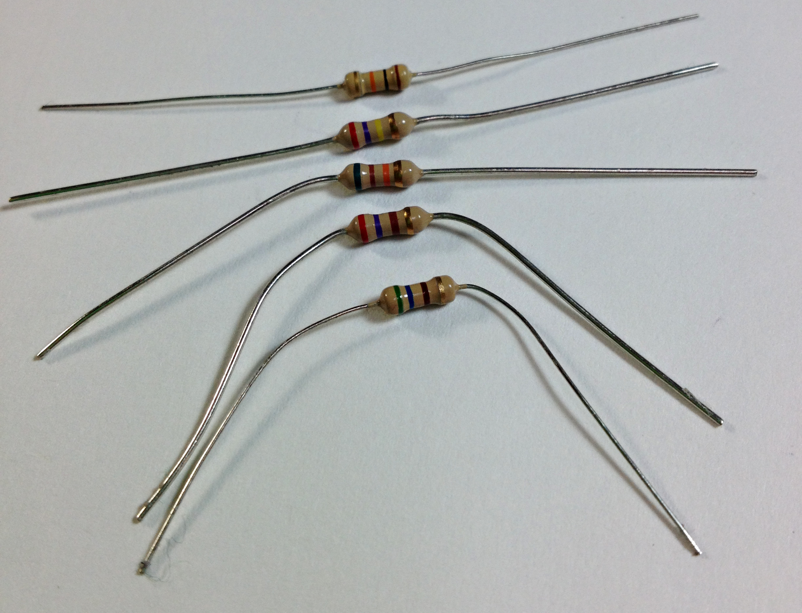
Take all of the resistors and line them up nicely.
If you are using the ones from the shopping list above, then you’ll want to line it up so the silver and the gold bands are all on the same side (right).
Make the following table in your notebook
|
|
Colour Band1 | Colour Band 2 | Colour Band 3 | Colour Band 4 | Nominal Resistance |
| Resistor1 | |||||
| Resistor2 | |||||
| Resistor3 | |||||
| Resistor4 | |||||
| Resistor5 |
fill in the colour band columns in the table starting with each of the resistors.
Now that you have all of the colour bands in, you can find the nominal values.
These colour bands are standard across all resistors. There are standard look up tables that you can use.
 |
| This one is from Michael’s learn Electronics site. |

To save time though,
There are a lot of calculators that you can either download on your iPod/iPhone or just use the web for it. I like to use this online calculator: http://www.eeweb.com/toolbox/4-band-resistor-calculator .
Fill in the tolerances using either charts or a nominal resistor calculator.
Now that you have all of the nominal resistance’s listed, it’s time to measure the values.
Get your multimeter.
The photo examples are for my multi-meter so it it may not be exactly what you are seeing.
Everyone’s will vary a bit, but it should be fairly close. Otherwise if you want to follow on exactly you can buy the same model I have Buy Here.
Turn on your multi-meter to check for power.

If you haven’t use your multimeter before I would recommend you to watch a few tutorials. I really liked the SparkFun one. It will really help understanding what kind of equipment you have.
Look for the Ohm sign. This helps tell you which part of your multi-meter is there to measure resistance. You usually only don’t use those sections for anything else. It should be on the multimeter a few times.
On mine it’s on there twice.

These two Ohm markings show 1.) Which are the set on the dial that we will be spinning to use. and 2.) where to plug in the leads (you need to really watch this when you start to measure voltages, but for now it’s okay).

Now turn the dial so it is in the Ohm section. The number isn’t important yet, but I would suggest putting it on 20K.

The whole time the screen should show a “1.”
This means that the resistance being measured exceeds what the multi-meter can read right now.
(e.g. too high or low of a level that it can understand).
e.g. When the leads aren’t connected to anything, then it’s almost infinite resistance, which is beyond what most equipment can read.
You may also get a 1. if you are reading a resistance that is too high for the settings. We’ll see one of these in the example.
Alternatively, you’ll see a 0 if the settings are too low.
Check that your lead tips don’t have covers on them.
Most of us lose the covers, but if you have a new one or by some luck haven’t lost yours (like I haven’t) then you may need to check this.

Now your multi-meter is on, the leads are in the right places, you have all of the resistors laid out, we’re ready to begin.
With the dial turned to one of the marks in the Ohm side (should be either a 200, 2K, 20K, 200K, 2M, 20M, 200M etc.), take the first resistor and put it on the table. Place one lead (red) on the left hand side and the other (black) on the right hand side.


Fun, but random fact (borrowing the wording from one of my close friends):
References:
eeweb Resistor Calculator: lots of good tools here
Resistors: by mikroelektronika
How to use a Multi-Meter from Afrotechmods on Youtube (also how to choose one)
More Advanced Resistors: Power Ratings from Kenneth at LifeofKenneth.com
